SERVICES OVERVIEW
Conventional NDT
The most common control methods, which allow us to investigate the different parameters of materials and processes.
Thickness Testing (UTS)
This is a technique that makes use of high-frequency acoustic waves, in the order of MHz for metallic materials, kHz for more heterogeneous materials such as stone and concrete. In particular, the purpose of the UTS technique is to detect the time of flight of an ultrasonic pulse and to obtain from this, indirectly, the measurement of the thickness crossed.
Defectoscope Testing (UTD)
This is a technique that makes use of high-frequency acoustic waves, in the order of MHz for metallic materials. In particular, the purpose of the UTD technique is to detect the time of flight of an ultrasonic pulse reflected or refracted by defects in the welds or in the structure of the parts examined. With the application of simple trigonometric rules, information on the positioning of the discontinuities present is obtained.
XR and YR Radiography
The X-ray radiographic technique (with X-ray tubes) or with γ-rays (with radioisotopes), is a precise and reliable method of investigation of volumetric type, his effectiveness has been well documented over time. Exploiting the phenomenon of the interaction of bodies with high-frequency electromagnetic waves generated by a source and detected by analog or digital films, it is possible to check with this technique artifacts of various types, shapes, chemical composition with the possibility of detecting internal defects, thickness variations, or anything else not reachable by the human eye. The progress made in the digitalization of the radiographic method, now allows greater sharing and reliability in the analysis of data.
Pros
– High degree of reliability
– Documentability over time and shareability of the images (Digital XRay)
– Possibility of highlighting internal defects
– Wide range of application
Cons
– Limitations on particularly complex geometries
– Limitations on the analysis of “opaque” materials or with very high thicknesses
– Safety limitations because of the use of ionizing radiation
Final results
The result of a radiography control is an “internal” image of the artifact analyzed by specialized and qualified technicians with decades of experience. Thanks to the digitalization of the system, the images can be shared and analyzed even remotely using dedicated software.
Magnetoscopy
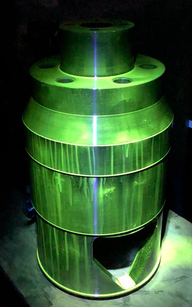
It is based on the attraction of ferromagnetic particles dispersed in a liquid that are attracted by the dispersed magnetic field near any defects, which remain trapped in it, outlining their contours and defining their dimensions.
The technique consists in the magnetization of the piece: in correspondence of indications a deviation of the magnetic lines of force is manifested towards the outside forming a dispersed flux. By sprinkling the workpiece with magnetic powders, either dry or in liquid suspension, these are attracted to the indication. The accumulation of such powders allows the detection of it.
Application fields and limits
The fields of application are various and range from visual inspection of piping for corrosion to simple final inspection to verify the correct cleaning of column bottoms or furnace coils. The two techniques can be combined in order to have more information, even if the combined use of the two techniques is not always possible since for the execution of thickness measurements the surfaces must have a medium to high degree of cleanliness. Visual inspections within equipment or pipes are usually performed at ambient temperatures, while it is almost impossible to perform examinations within pipes flooded by alkalis or acids, because of the serious damage they can cause to the on-board electronics.
Final results
In case of video-inspections, paper reports will be delivered together with the recorded videos; the paper report will always indicate the general conditions. In the case of UTS inspections, the summary report will be composed of a table containing the numerical data measured in the various examination positions and, if requested, the B-scan of the inspected areas will also be attached.


